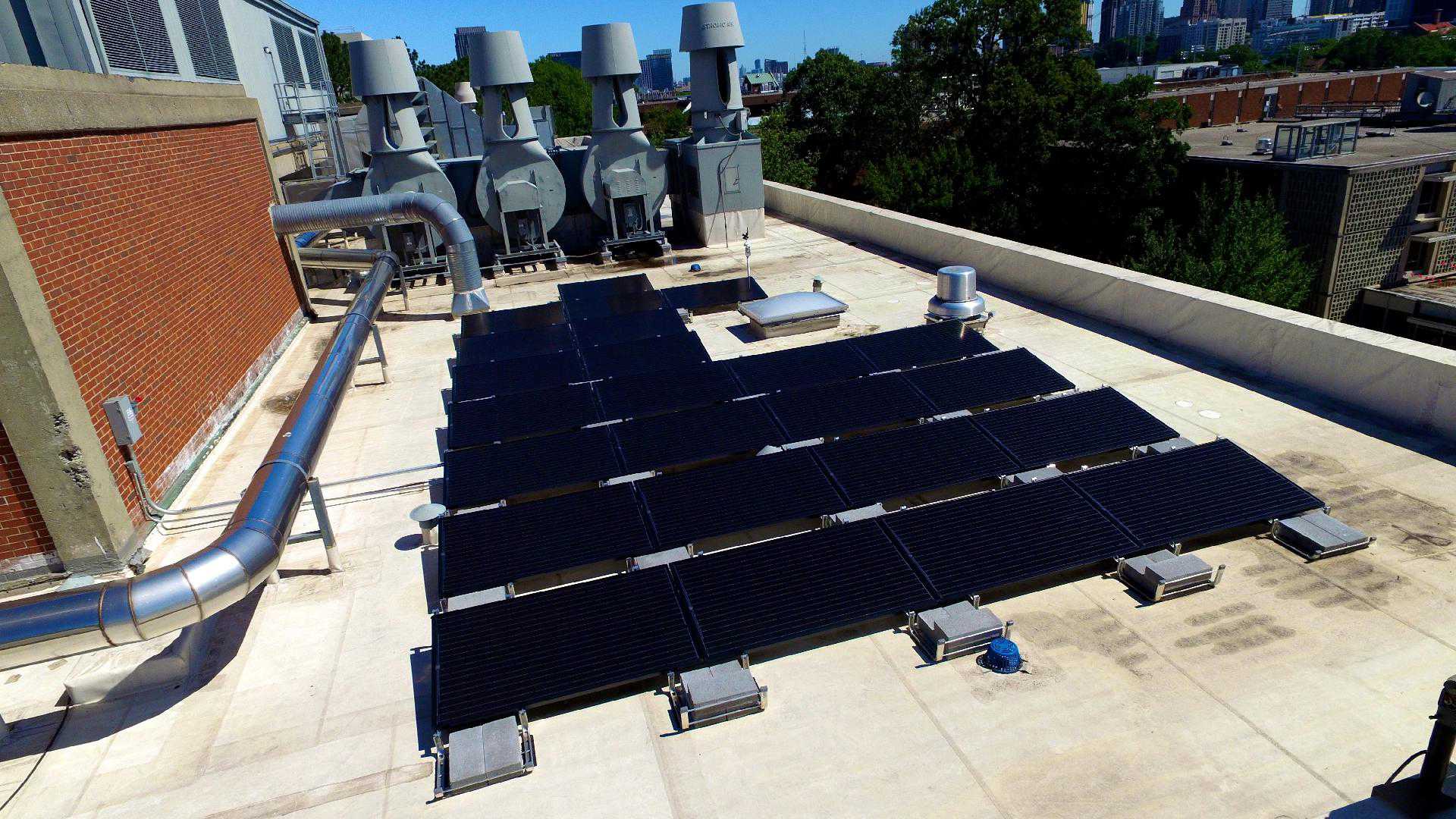
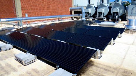
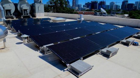
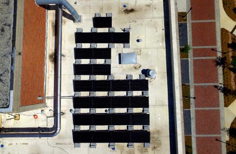
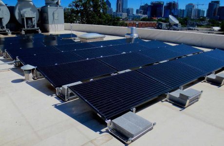
6.72kW PV Array
24 x 280W Solarworld SW 280 PV Modules
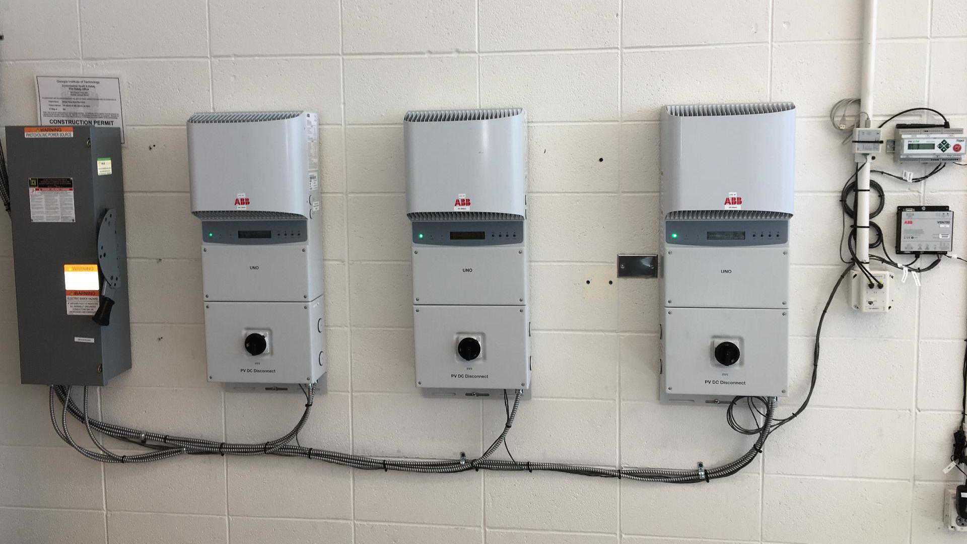
3 x ABB PVI 3.6kW Inverters @ 277VAC
24 x Tigo TS4-R-S Safety/Monitoring Modules
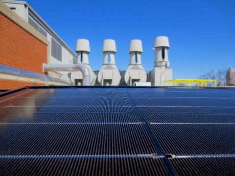
ABB Weatherstation
georgia_tech_bh_solar_front_view_1920x1080_q5

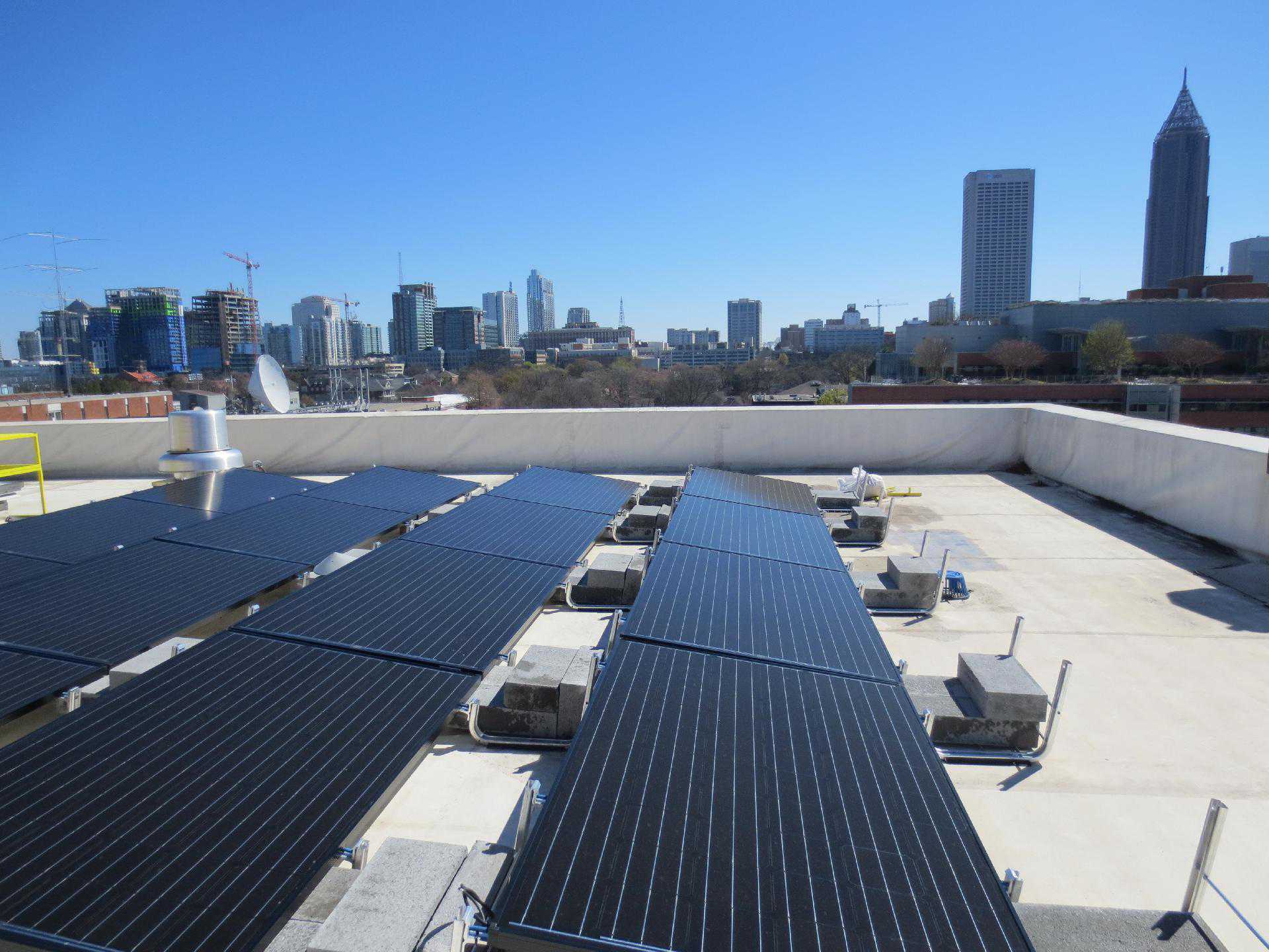
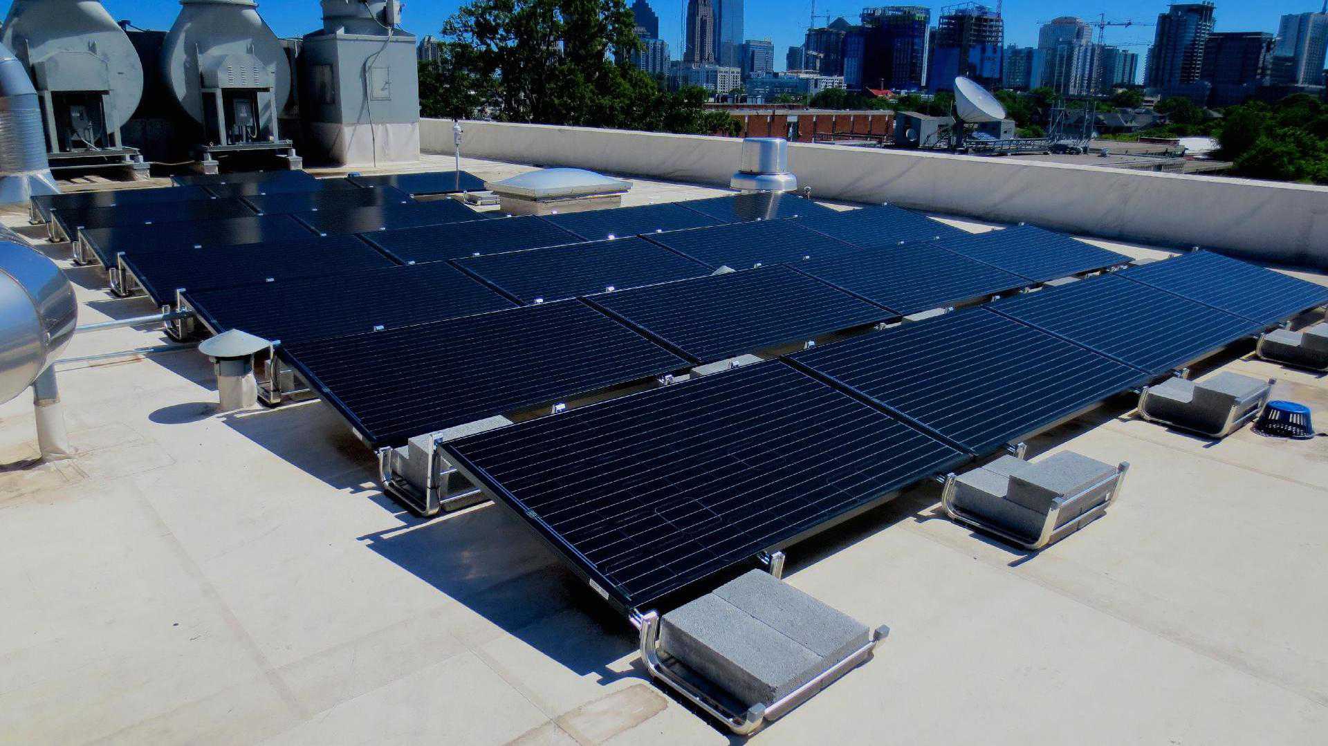
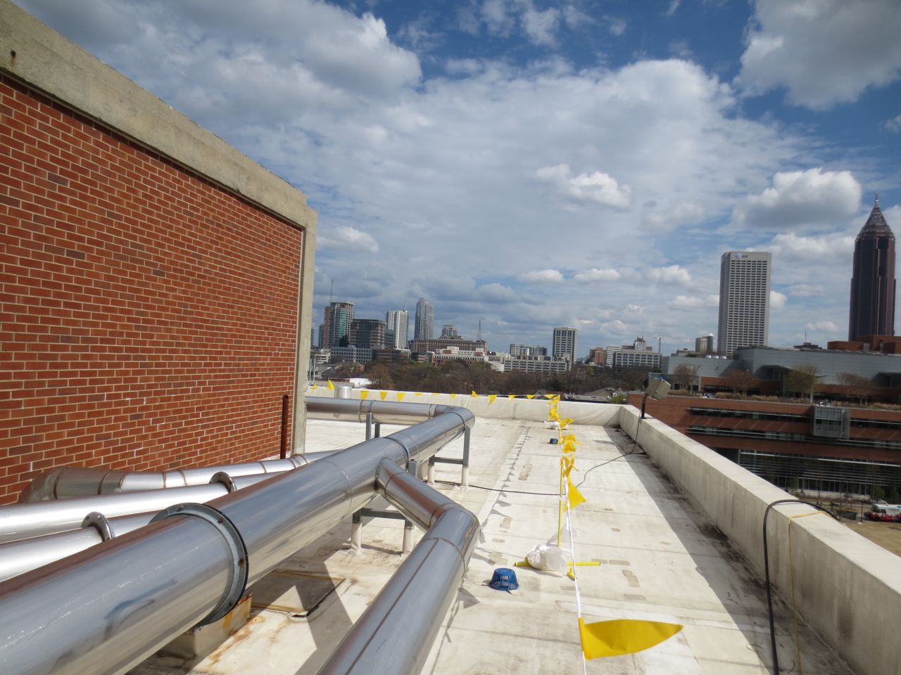
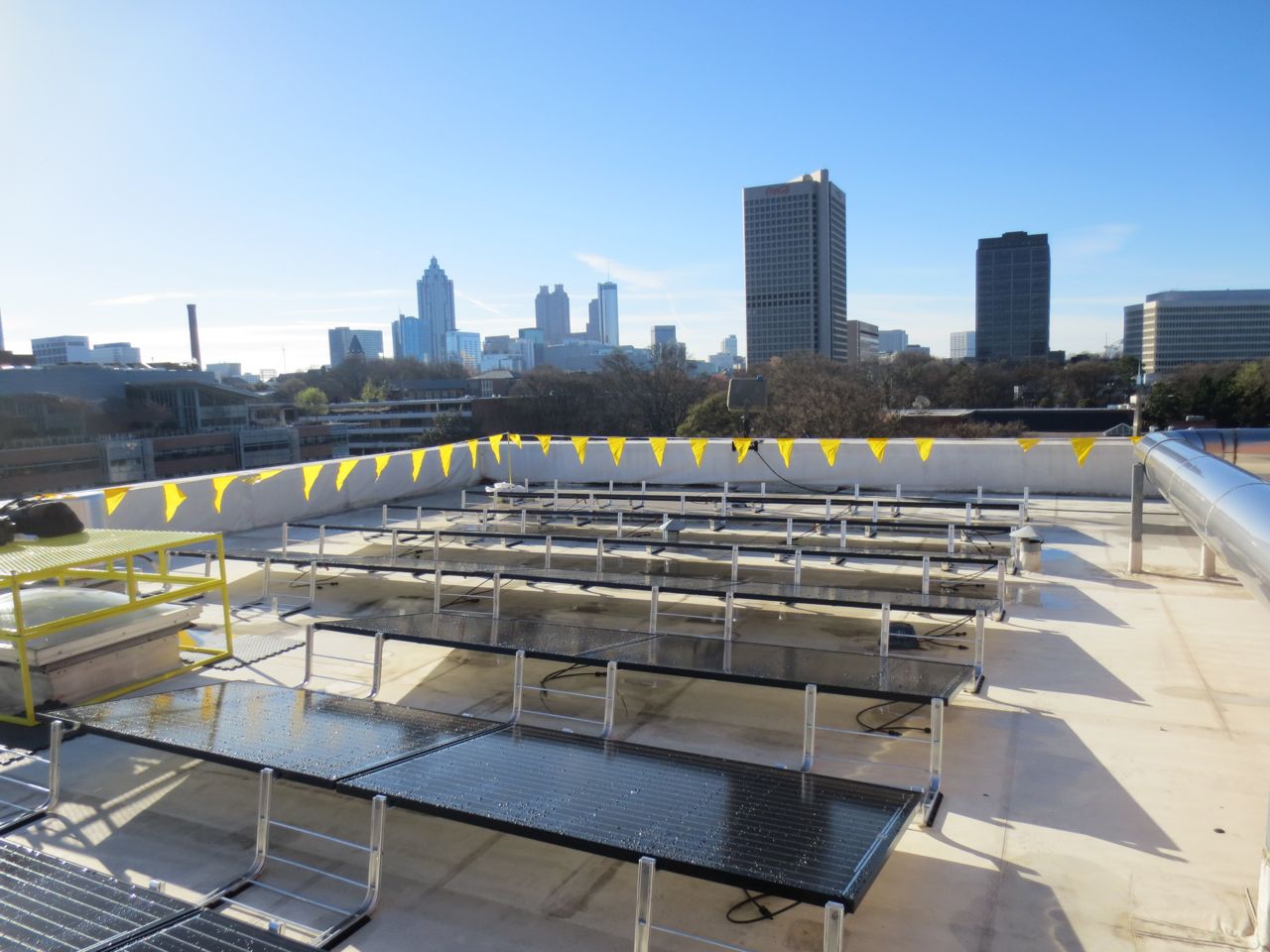
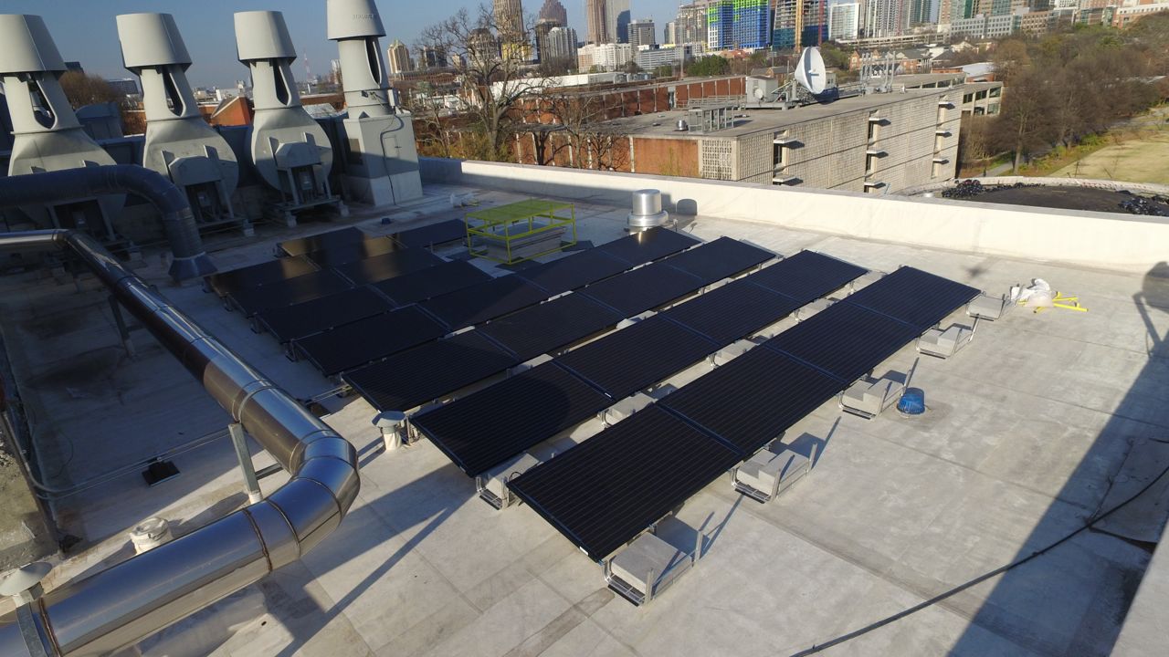
gerogia_tech_bh_solar_sideview_city_1920x1440_q5
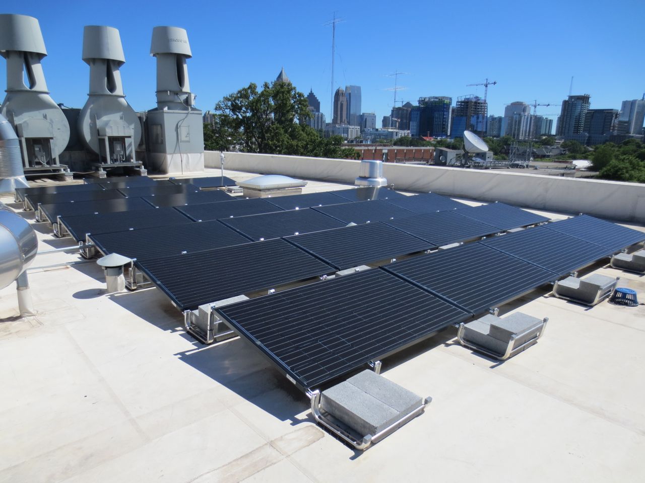
georgia_tech_bh_solar_rooftop_array_and_disconnect_1920x1079_q5-1

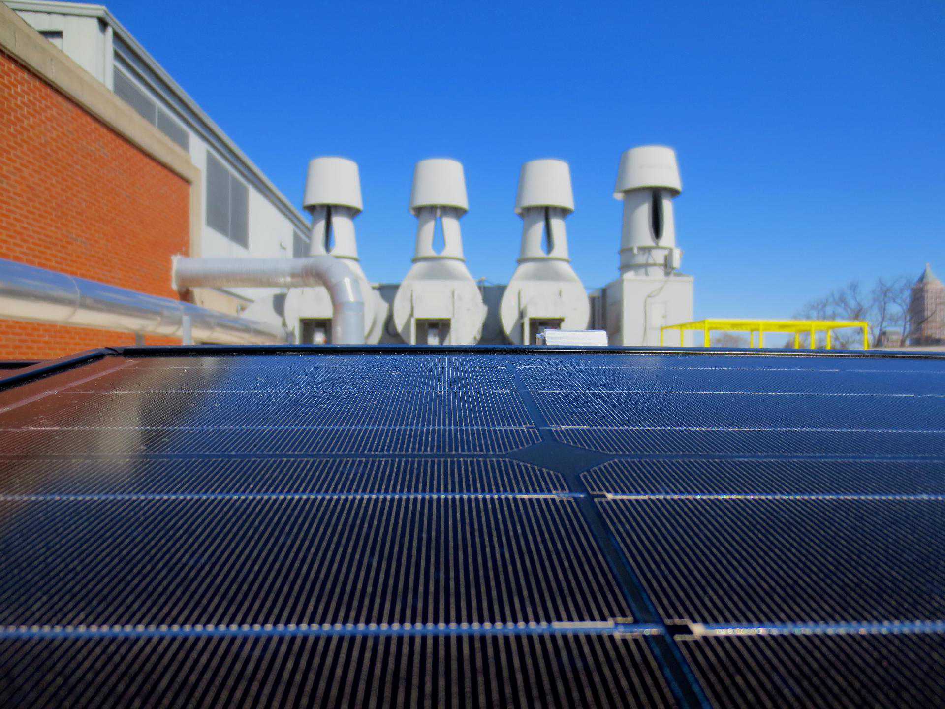
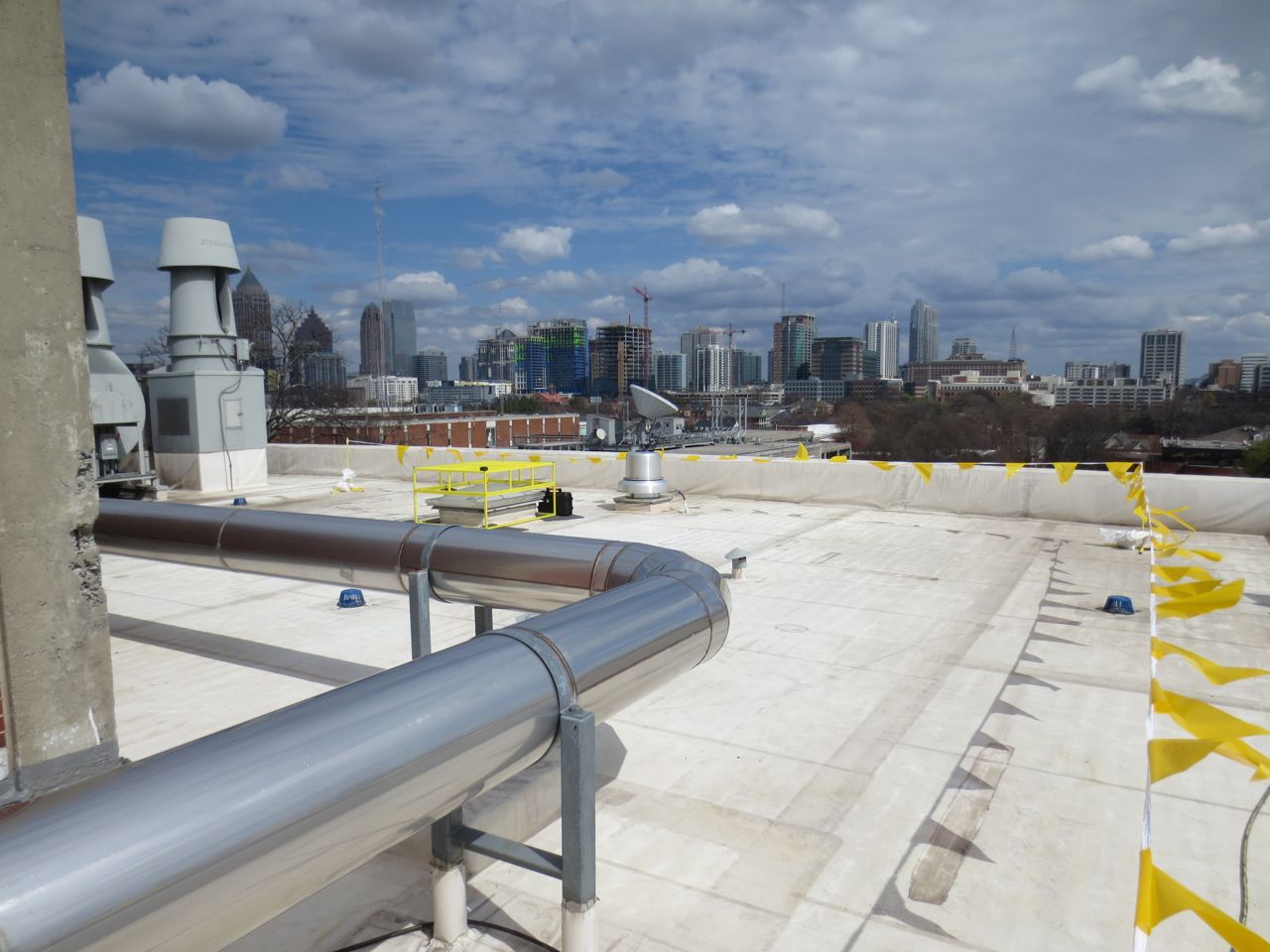
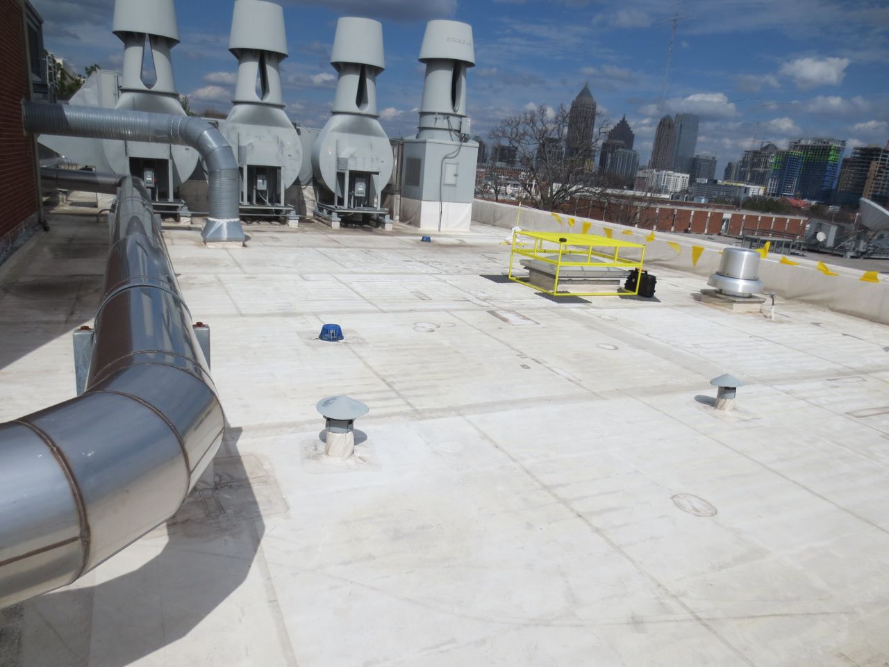
georgia_tech_bh_solar_vents_1920x1440_q5
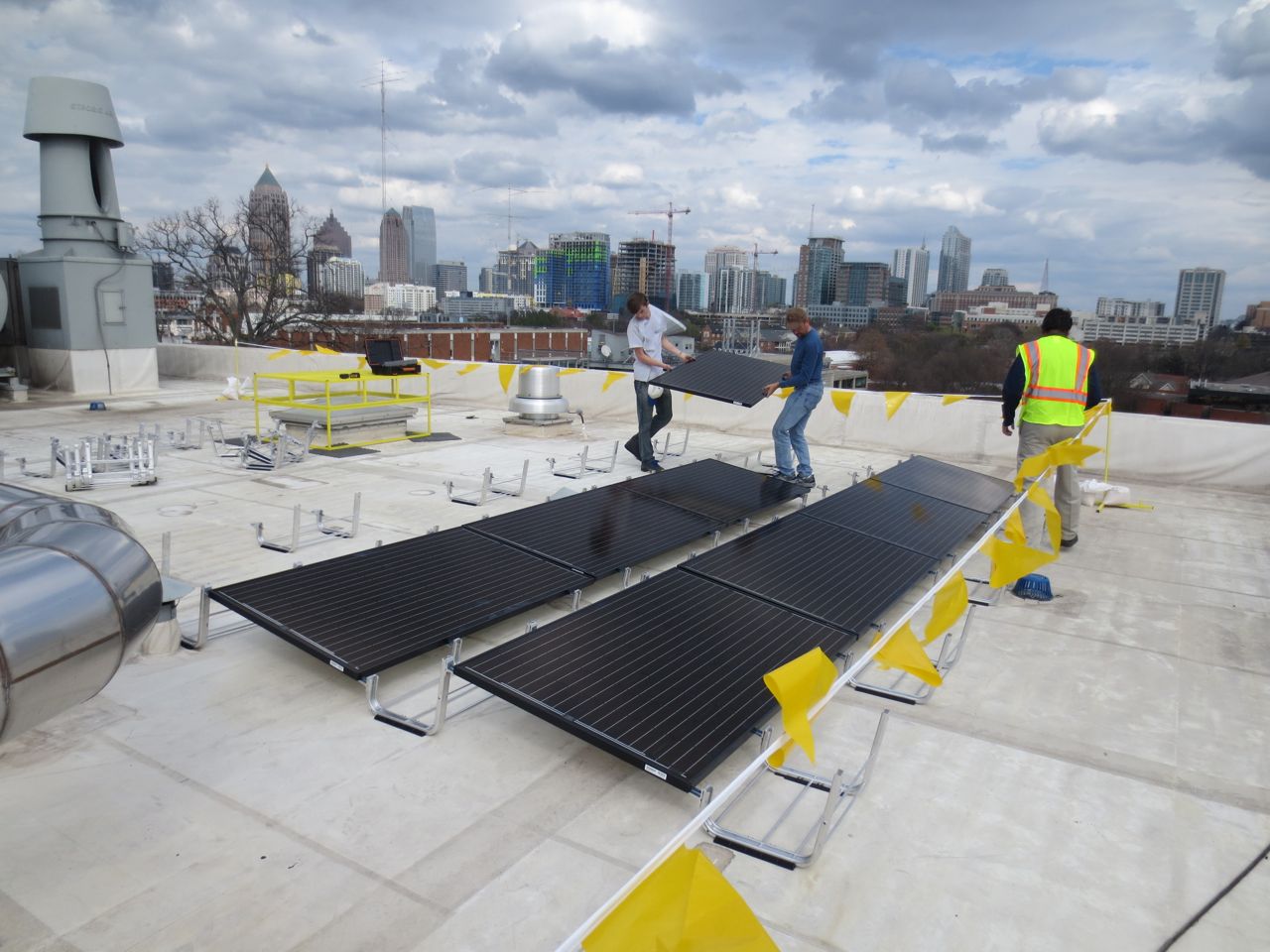
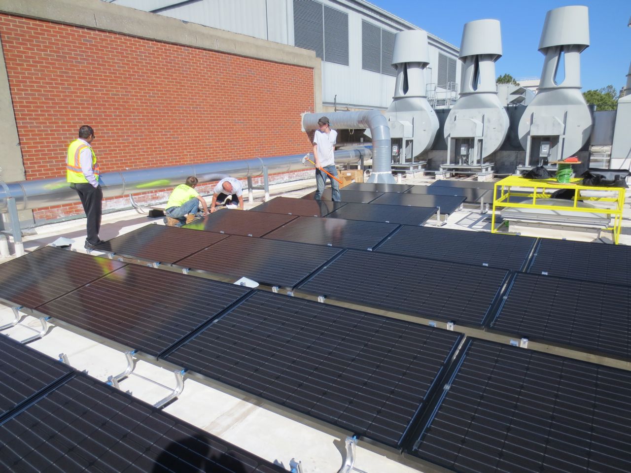
georgia_tech_bh_solar_lab_installation_1920x1080_q5
georgia_tech_bh_solar_diag_view_city_1920x1079_q5
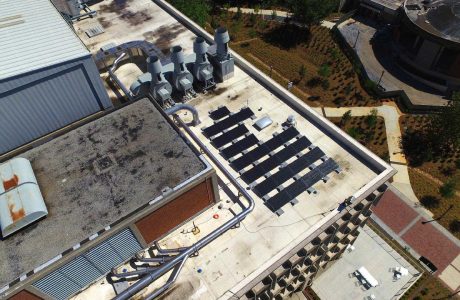
georgia_tech_bh_solar_aerial_view_1920x1080_q5
georgia_tech_bh_solar_aerial_side_1920x1080_q5
georgia_tech_bh_solar_aerial_building_1920x1080_q5
System Equipment & Monitoring Tools
PV Modules
24 x Solarworld USA 280 Watt PV Modules
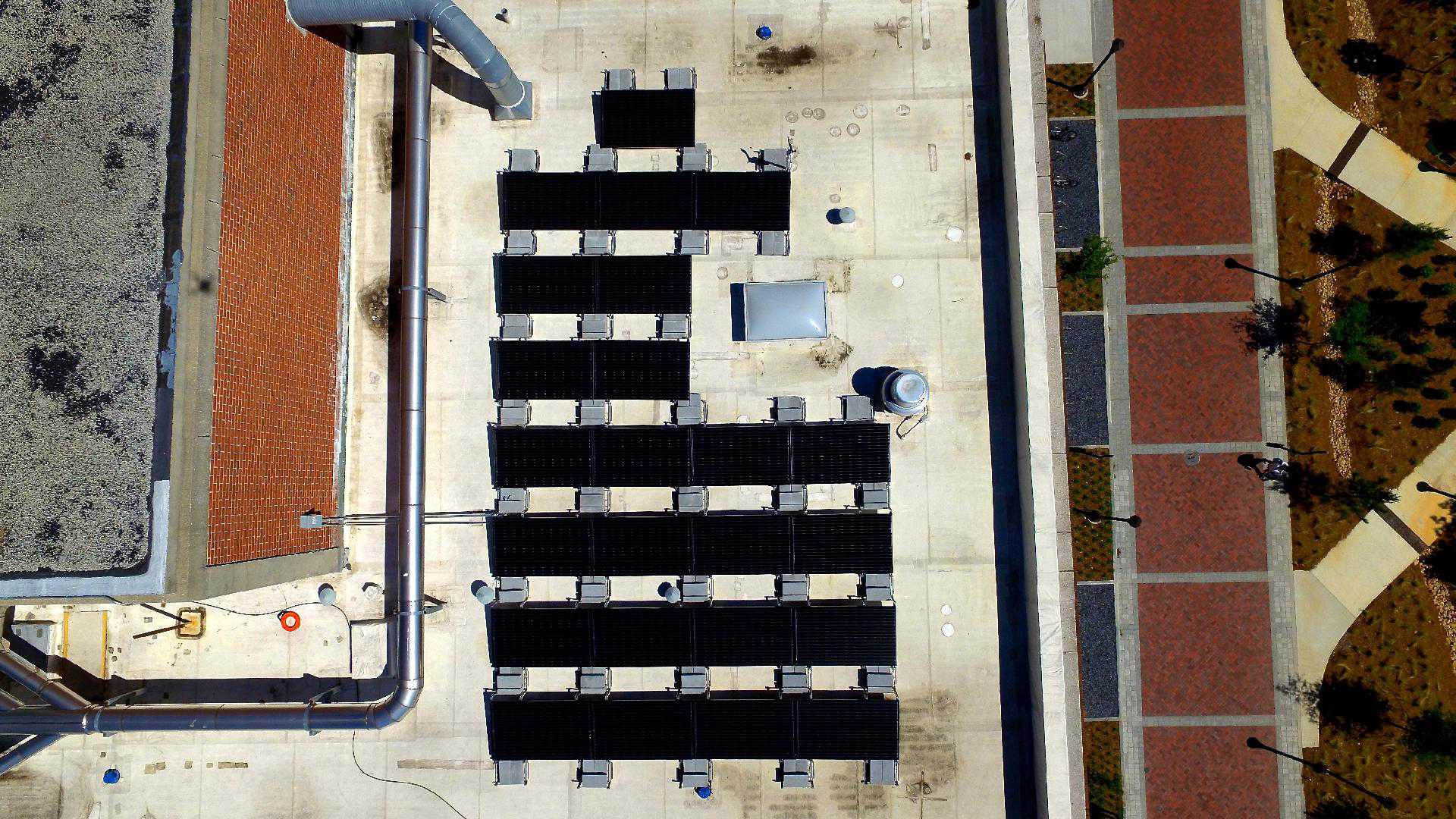
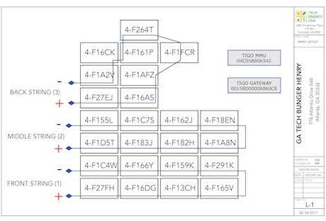
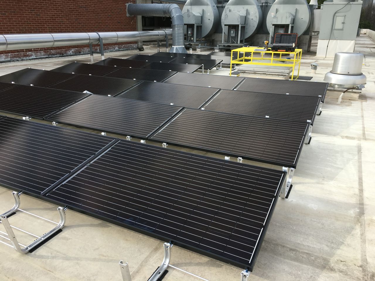
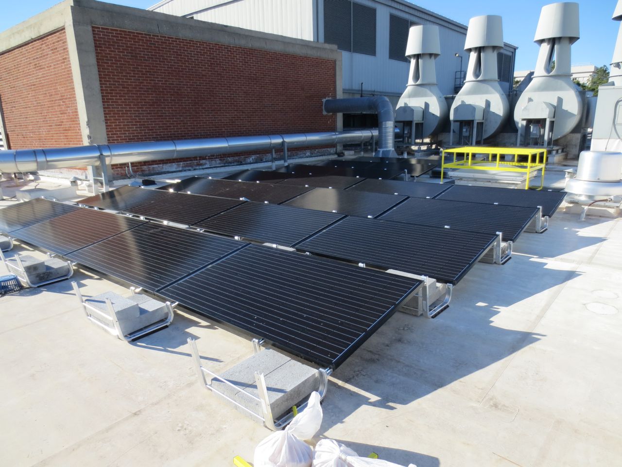
The solar array consists of 24 modules arranged in 3 strings of 8 modules each.
PV MODULE DATASHEET
PV Inverters
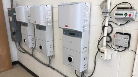
3 x ABB PVI-3.6-TL-OUTD-US-A
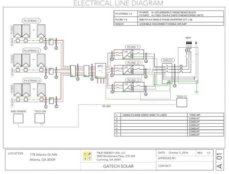
The PV system uses 3 single phase ABB inverters, each feeding back to a different phase of a 480Y/277V service.
PV INVERTER DATASHEET
Racking
UNIRAC RM-10 Ballasted Racking
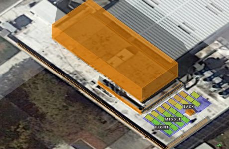
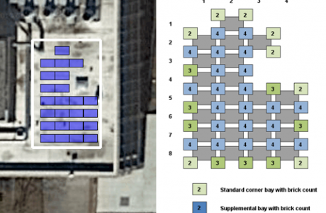
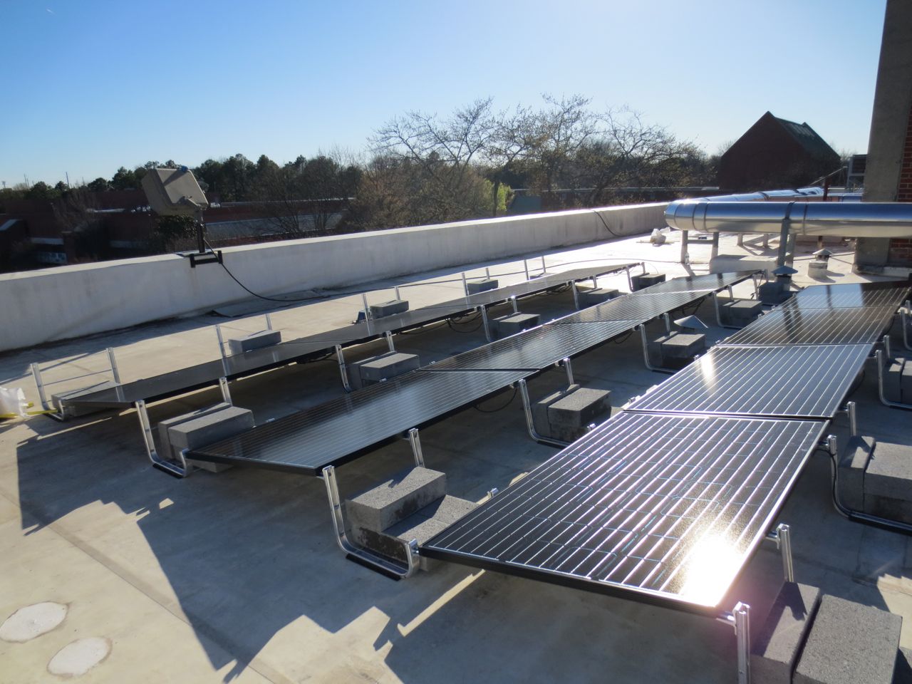
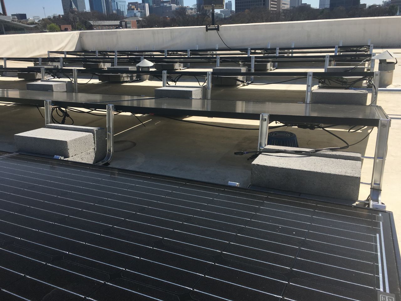
The ballasted racking consists of 38 ballast bays containing 128 4x8x16 cement blocks.
RACKING DATASHEET
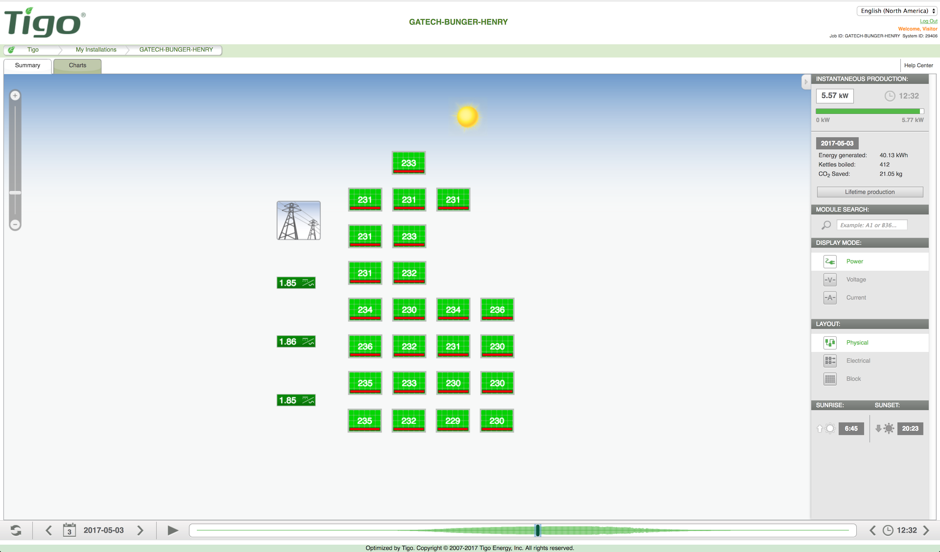
Module Level Monitoring
24 x TIGO TS4-R-S Safety/Monitoring Modules
Each PV module attaches to a TIGO TS4-R-S Safety/Monitoring unit that provides module level monitoring and rapid shutdown capability.
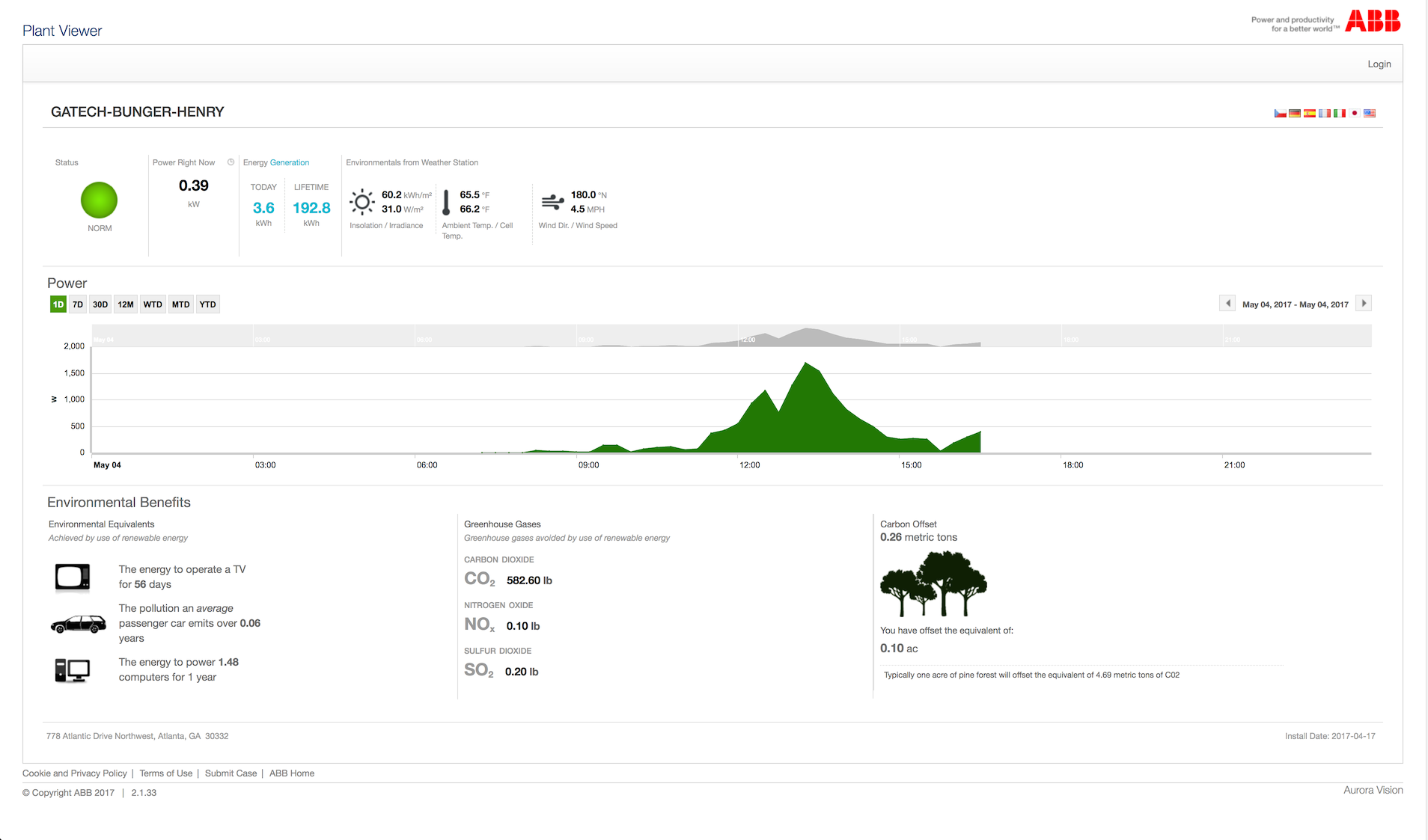
Inverter Monitoring
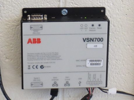
ABB VSN700-03 Data Logger
The ABB Data Logger provides logging and internet access for inverter output from all 3 PV inverters in the system as well as weather station monitoring.
DATA LOGGER DATASHEET
TIGO Cloud Connect
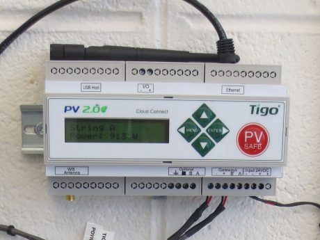
TIGO Cloud Connect
The TIGO Cloud Connect provides logging of TIGO module level monitoring data. If also acts as an internet gateway to upload data to the TIGO web monitoring portal.
CLOUD CONNECT DATASHEET
Weather Station
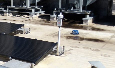
ABB VSN800-14 Weather Station
The ABB Weather Station provides instantaneous reporting of local weather conditions at the array location.
WEATHER STATION DATASHEET
Inverter Web Monitoring

ABB AuroraVision Web Portal
The ABB AuroraVision Web Monitoring portal provides online monitoring of ABB Inverter and Weatherstation data. Inverter data is stored at 15 minute intervals.
VIEW SITE
Module Web Monitoring

TIGO Web Monitoring
The TIGO Cloud Connect Gateway provides web based monitoring and historical data access to module level monitoring data form the array.
VIEW SITE
TIGO MONITORING DATASHEET
Physical System Design
Design Restrictions
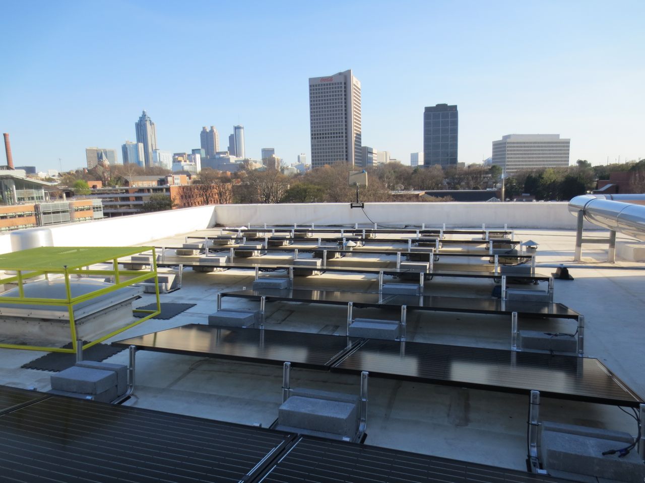
The Bunger-Henry PV Array layout was designed with the fllowing goals:
- optimize the use of available roof space
- avoid existing fixtures such as waste vents, roof drains and skylights
- maintain code compliance by providing adequate access pathways required by fire code.
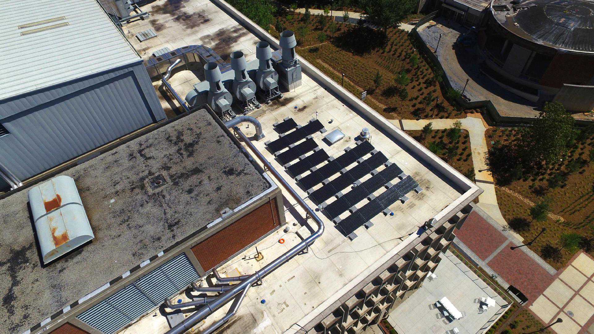
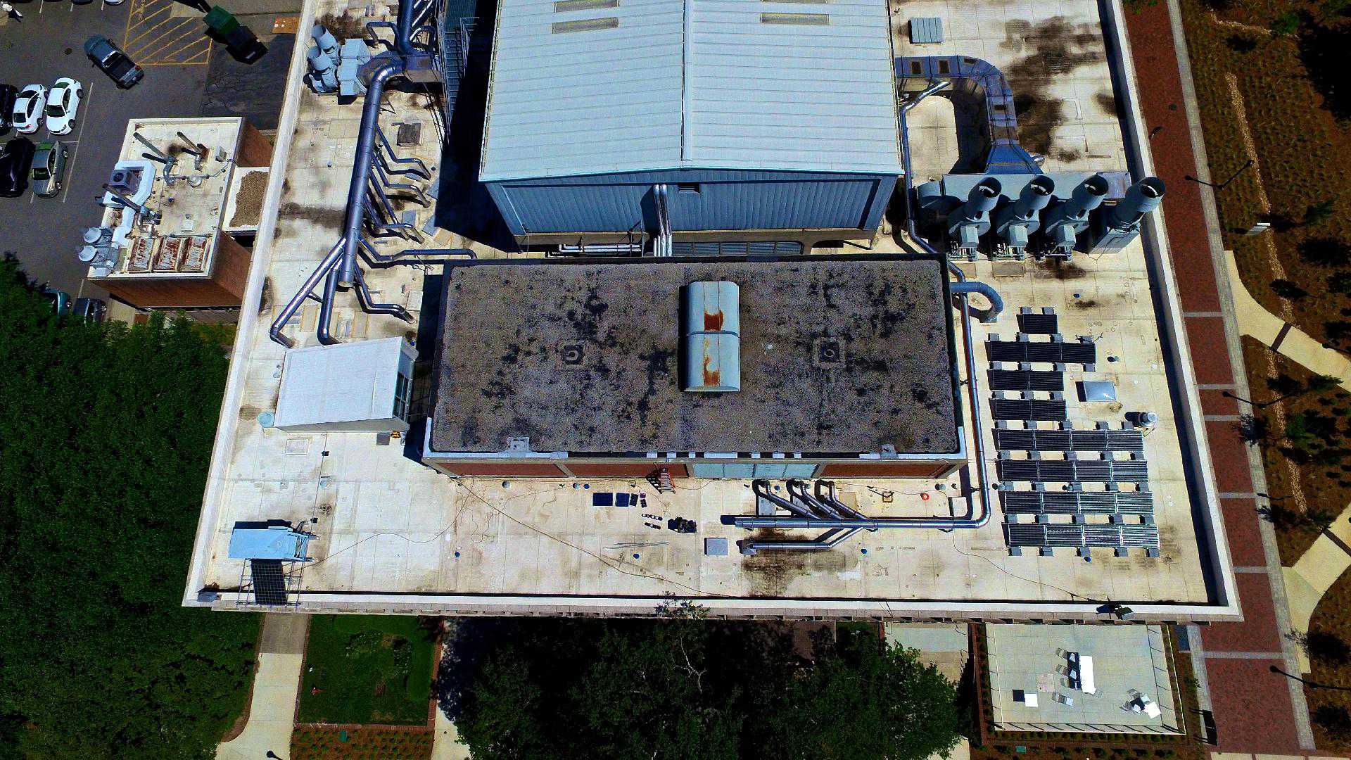
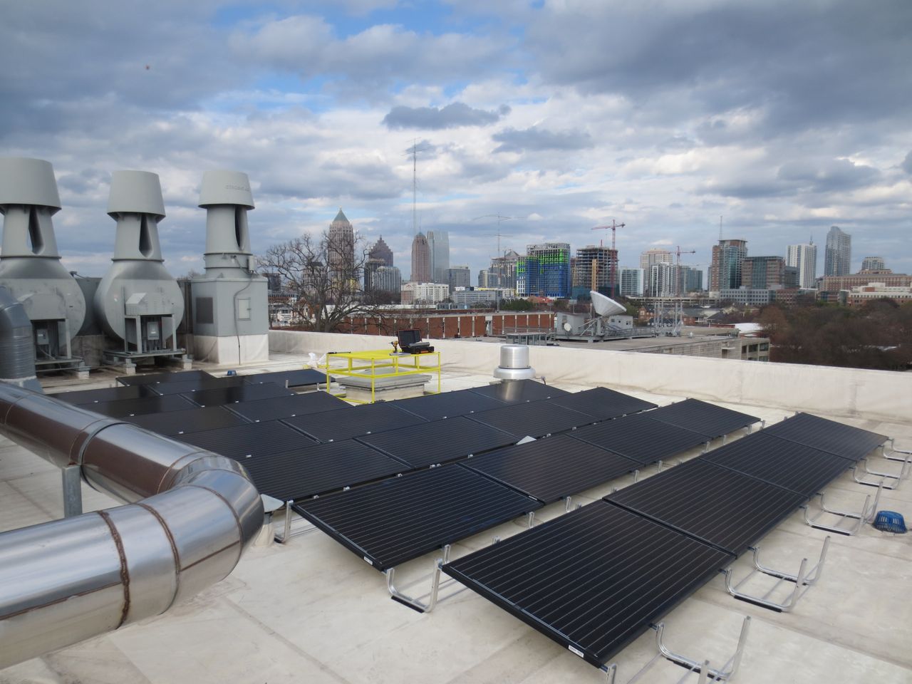
While the location and layout are not optimal due to shading from the nearby penthouse and ductwork, it is more than adequate for research purposes.
Azimuth, Tilt, Production & Shading
The Bunger-Henry array has the following orientation and tilt:
- Azimuth: 180 degrees
- Tilt: 10 degrees
The 180° azimuth is perfect for solar generation and the 10 degree tilt, while not optimal is used in order to allow for lower ballast loads. While a 30-35° tilt angle would be optimal for this location, it is not practical for ballasted systems due to the additional wind loads incurred and extra ballast that would be required. See the following simulation reports.
HELIOSCOPE PRODUCTION SIMLATION REPORT
HELIOSCOPE SHADE SIMLATION REPORT
Ballasted Racking Design
Since this system was to be installed on a flat roof, a ballasted racking system was chosen. These systems use a ‘ballast’, in this case 4x8x16 cement blocks, to weigh down the array. The amount of ballast is calculated based on wind loads for the area and terrain. One of the main benefits of a ballasted racking system is that it does not require any roof penetrations so the chance of roof leaks are kept to a minimum.
The racking design was provided by the UNIRAC online design tool. The design tool takes visual layout of the array along with the location, height and other parameters then applies ASCE (American Society of Civil Engineers) (ACSE 7-05 & ACSE 7-10)and IBC (International Building Code) standards for wind, snow and seismic loads to arrive at the specific ballasted design.
SEE RACKING DESIGN REPORT
Structural Engineering
Since any rooftop PV system, ballasted or attached, imposes an additional load on the building structure, a structural engineer needs to examine the building structure as well as evaluate wind, snow and seismic loads to make sure that the building can support the additional loads and that the array design will withstand the wind and seismic loads. For commercial designs, a stamped PE letter from a structural engineer is generally required.
PE LETTER: BUILDING LOADS
PE LETTER: RACKING DESIGN
PE LETTER: POST INSTALLATION
Electrical Design
Electrical Design Parameters
The basic design requirements are as follows:
- 480Y/277V Three Phase AC Service
- Power Factor adjustable on a per phase basis
- Module level monitoring
- Monitoring/data logging capability
- NO module level optimization
- Approximate 300′ run from array to inverters
- Generation inconsistencies per phase are fine
PV Array Strings
In order to accommodate the requirements for 480Y/277V and per phase power factor adjustment, 3 ABB-PVI-3.6 single phase 277V inverters were selected. Due to the roof space limitations and minimum voltage requirements, a single string of 8 modules per inverter was the optimal choice. The map of Tigo modules and wiring is shown in the following document.

Electrical Engineering Diagrams
Based on the electrical design parameters and equipment selected, the electrical engineer provided a stamped engineering package including the line diagram, wiring charts physical system layout and code compliance lists.
Engineering Package
Any PV installation should be in compliance with the National Electric Code (NEC), International Fire Code (IFC), International Building Code (IBC) and International Energy Conservation Code (IECC). The engineering package contains the code list of the different applicable codes along with data sheets, engineering documents and other information.
ENGINEERING PACKAGE
User Guides & Information
System Installation Gallery


Final System Photo Gallery